Counterpoint SA-100 BJT Output Stage
In early 2020, I bought another non-working SA-100 with the idea that I would finally build a BJT output stage. Exicon MOSFETs are awesome without a doubt, but they are still MOSFETs and come with a characteristic FET sound - I wanted to try BJTs. It was my intention to use the original biasing circuit/vbe multiplier on the mainboard to bias the transistors to reduce the number of parts to be changed and to make the job simpler. It was a good idea, but in execution it was impossible to balance the DC and bias - one too greatly affected the other.
I could not figure out how to control the DC passively using the existing circuit, so I employed opamps to monitor and correct the DC offset actively. I was initially excited to use a DC servo, but constructing it deviates considerably from the simplicity of using the original circuit. In fact, it's a bit tricky to get good behavior from such a solution, and even then, this added complexity comes with its own imperfections. None the less, this appears to be the right soulution for this particular circuit.
I modeled approx ten different output stages, built two and settled on the one with the lowest distortion. In the first build, which used most of the original bias circuit, I saw massive distortion in the low end and the frequency response had a little rise at the very top. I was rather disappointed by this performance and thought my modeling was to blame. Ends up that Stereophile tested the SA-100 many years ago and got the same weird bumps and rises in the curves.
The high frequency bump is due to a 820 pf capacitor in parallel with a V1a's cathode resistor - remove the cap, and the bump flattens.
The rising distortion at low frequencies is due to the pair of coupling capacitors connecting the driver stage to the output stage. I suspect that the paralleled caps are responsible.
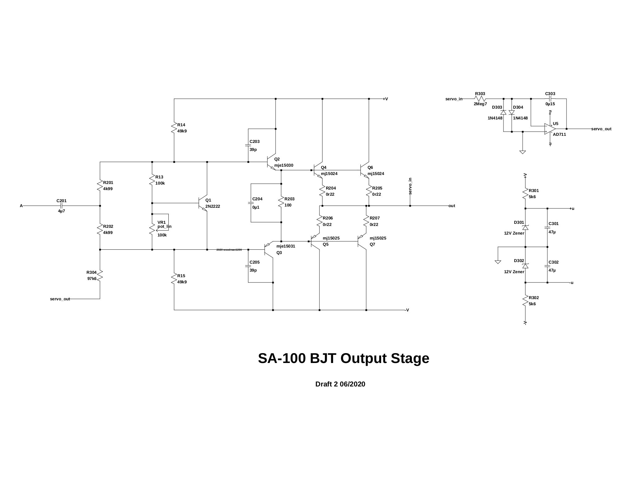
In order to lower the distortion at low frequencies, a single coupling cap is inserted between the driver and the output stage. C3 and C4 must be removed and replaced with two resistors. So far, this stage performs much better than the first one. It has relatively flat frequency response and distortion curves. The distortion stays below .4% THD+N at 10W into 8 Ohms from 20Hz to 20kHz. The driver stage was also modified to resemble the SA-220 driver stage.
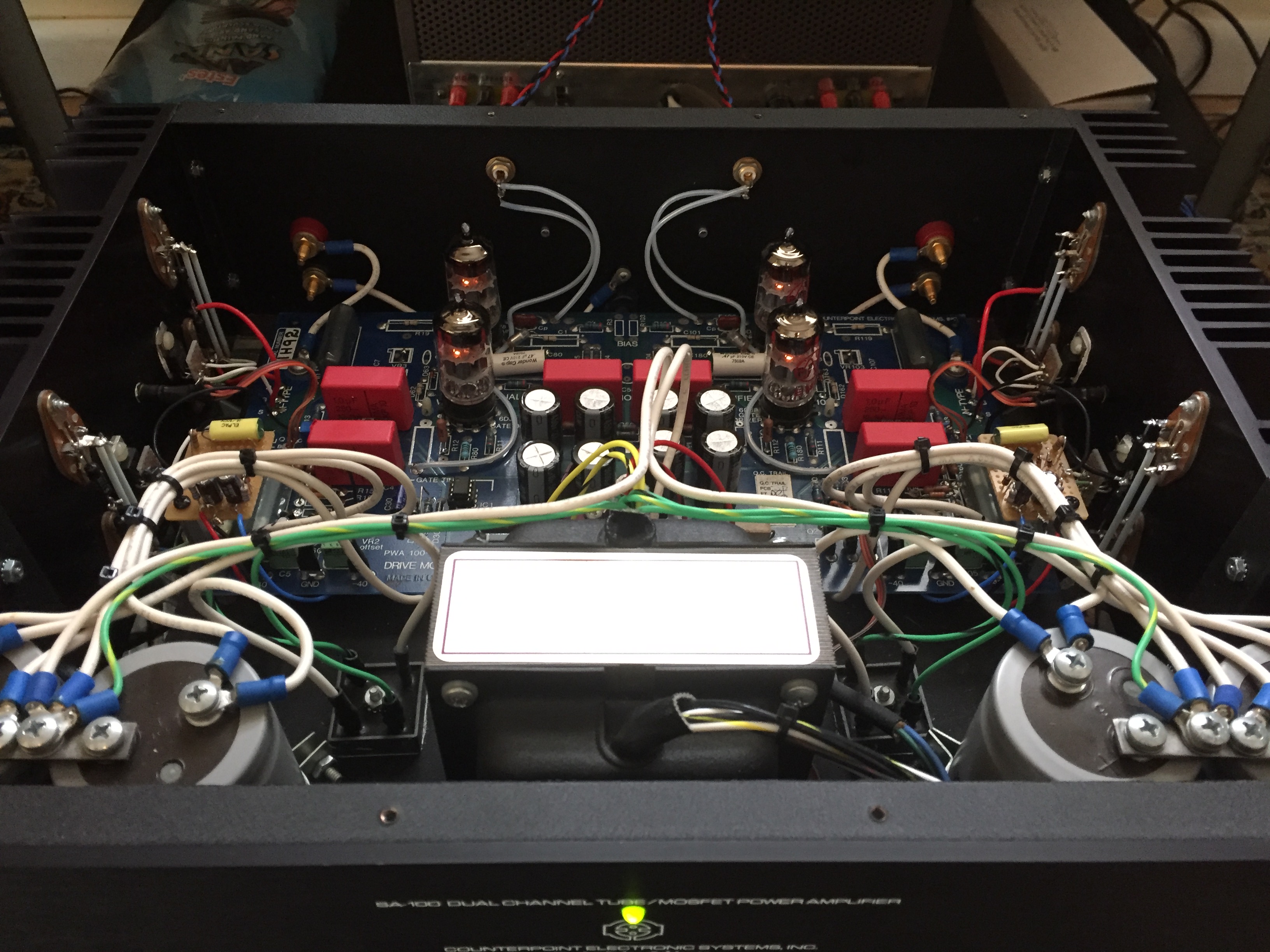
Here is my BJT output stage for the SA-100. The SA-100 BJT, so far, seems more stable and rugged than the original. It has overall lower distortion, particularly in the bass which comes across as being considerably cleaner, faster and deeper sounding than the original. Of the SA-100s that I have owned, this SA sounds closest to how I remember the SA-220 sounded, but without inbuilt euphonics.
I have been listening to this amp for a few months now and have done enough testing to feel confident about posting the output stage schematic. Of course, there are still many ways to make this circuit even more stable/faster/accurate/safer, but as I have learned what I wanted to learn from this project, I am going to leave this circuit as posted for anyone to try (at their own risk).
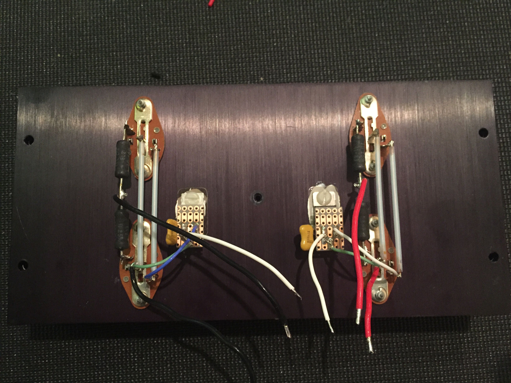
Original heatsik with MOSFETs
Modified heatsik with BJTs. Two #6-32 holes were tapped for the driver transistors.