Counterpoint SA-12... with a BJT Output Stage
The SA-12 is the predecessor to the SA-100. This amplifier has the same output stage, power supplies, and control circuitry as an SA-100, but has a smaller transformer, lower +/- rail voltages, and the driver stage is completely different.
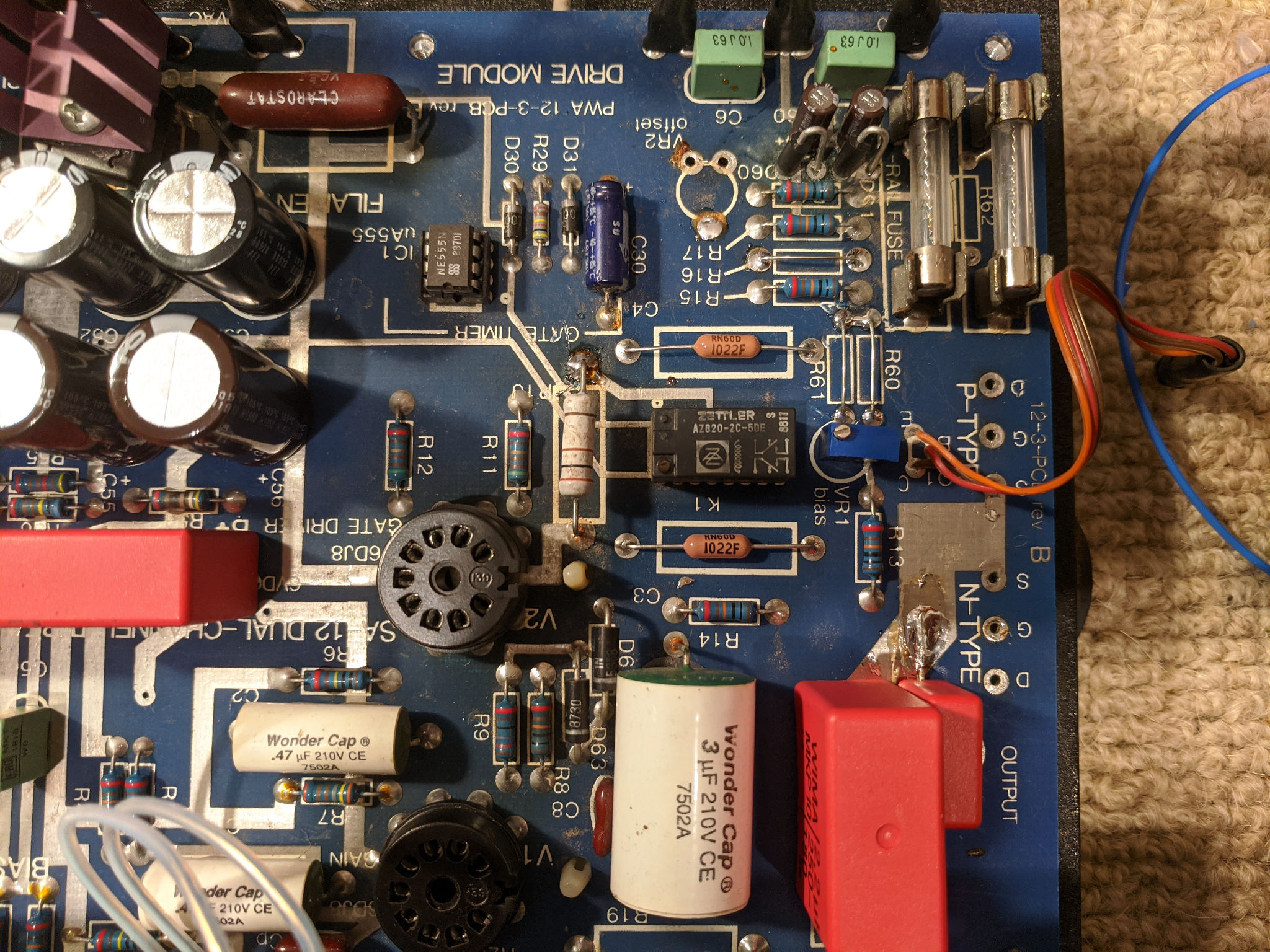
In researching this amplifier, I discovered that there were at least two different versions. I had the schematic for the (presumably) first version, but my SA-12 did not match up. Just a quick look at the input/driver board shows two more Wondercaps than indicated.
The 2nd version of the SA-12 has the paralleled driver stage with its own cathode resistor and feedback ac coupled to the cathode of the input tube. The first version has the feedback path DC coupled through a 30k resistor and a shares the cathode resistor of the input tube.
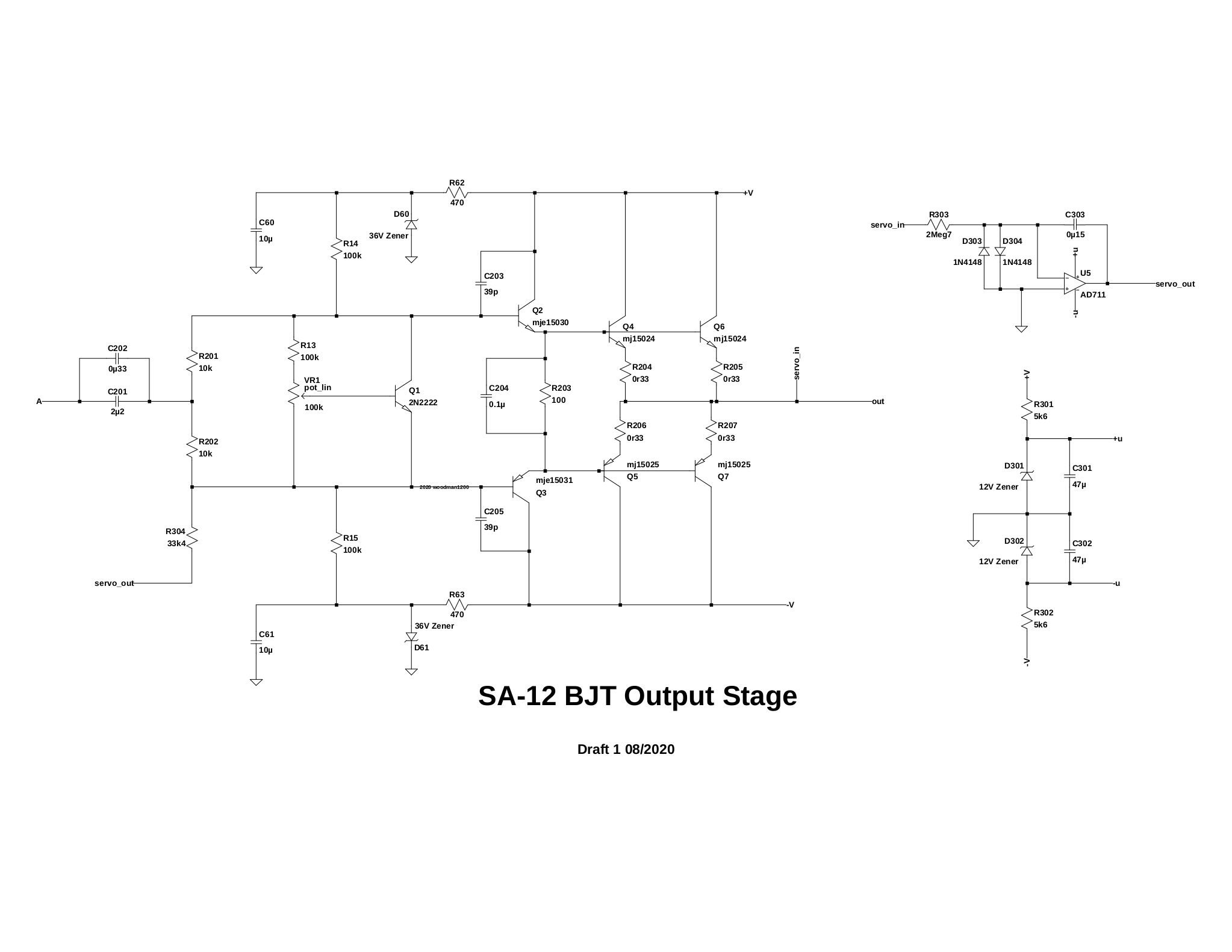
I used nearly the same output stage topology as the SA-100 BJT on the SA-12 - the zener regulators and some of the original bias resistors remain. I also put the DC servo and output circuitry all on one board - I am considering having some PCBs made as I now have a few SA amplifiers that require new outputs.
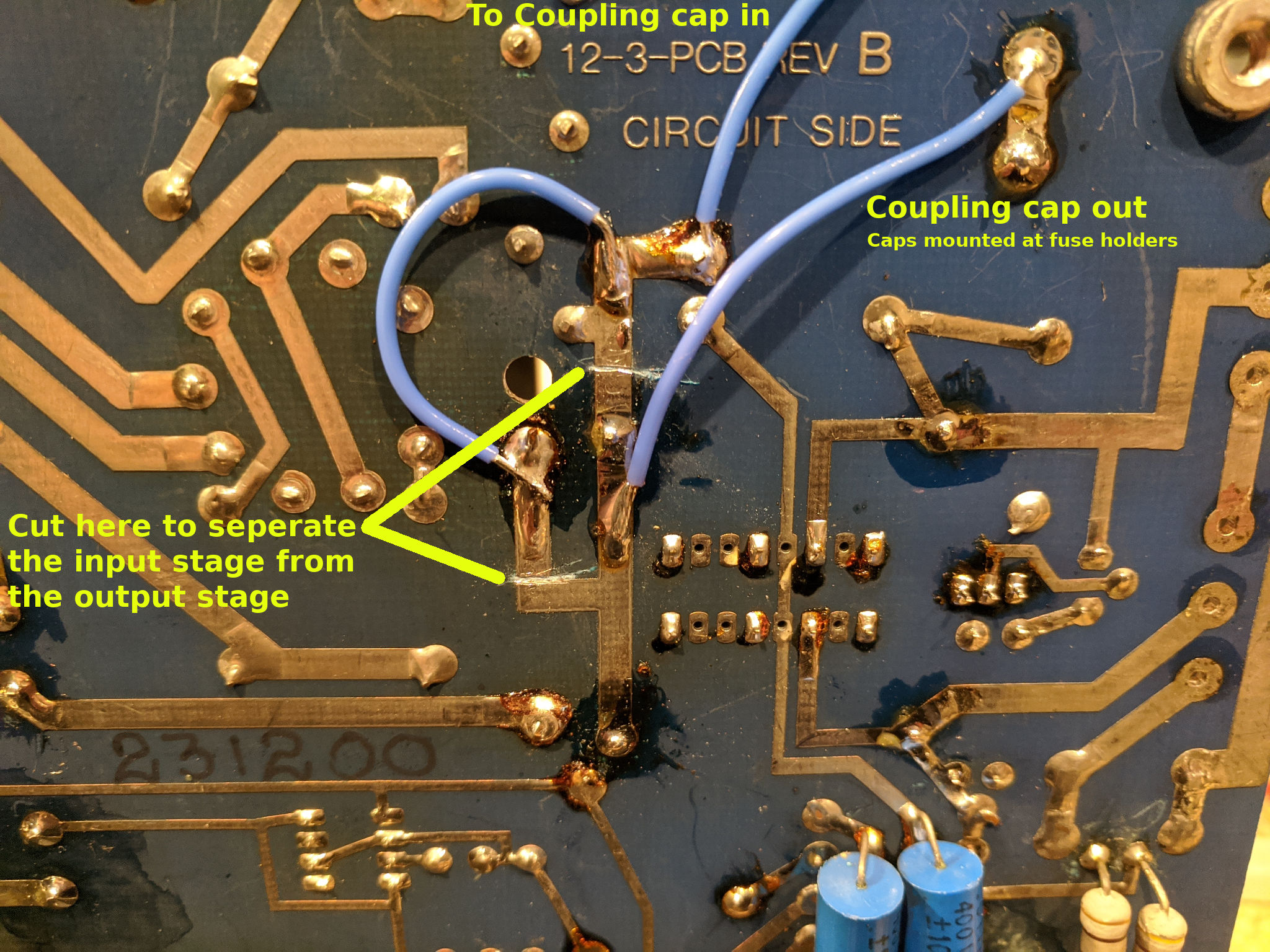
The SA-12 is considerably easier to work on than the SA-100 in terms of seperating the input stage from the output stage.
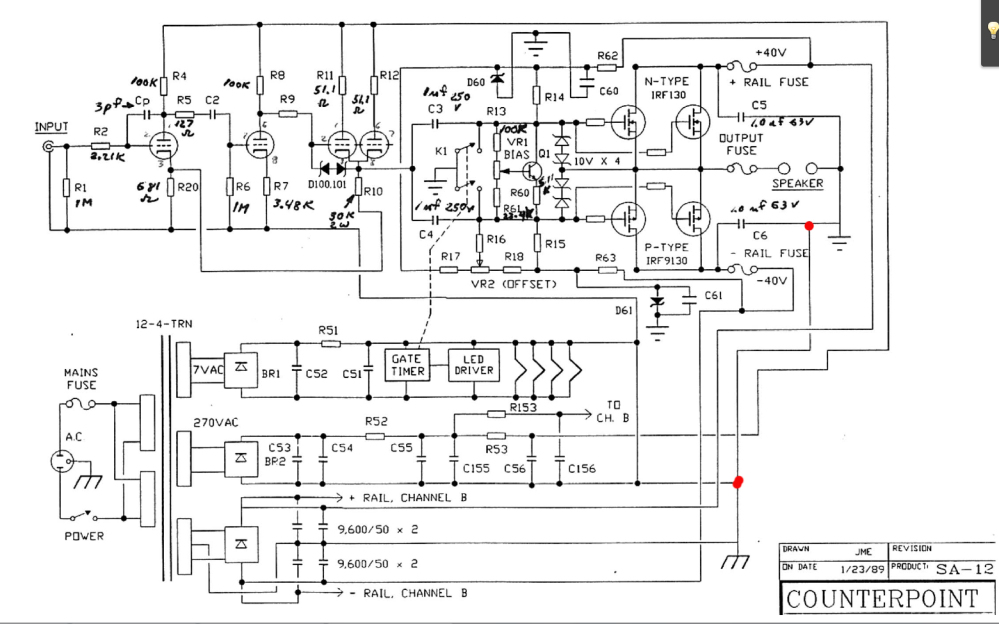
Original Counterpoint SA-12 schematic
BJT output stage for the SA-12 (not recommended for rebuild - see below)
Like the SA-100, the SA-12 has the same the same rising distortion at low frequencies, so cutting the traces between V2 and C3/C4 to insert a new coupling cap is necessary. C3 and C4 are replaced with 10k resistors.
Stereophile SA-100 THD vs Freq.
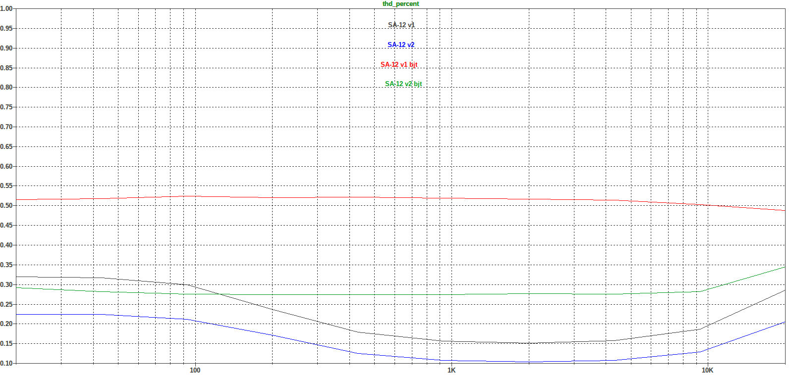
An unavoidable characteristic of the SA-12 driving BJTs is that distortion increases considerably as power is increased. The distortion at 1W is much less than at 10W which is much less than at full power. This trend is much more pronounced with transistors than with MOSFETs (according to my models). I measured near 4% THD at full power with my BJT output stage in the SA-12. It would seem that this driver stage cannot adequately drive the output stage as the distorted waveform can be seen at the coupling cap.
Percent distortion (at output) vs input voltage. This is a modeled comparison of the BJT stage and the MOSFET stage in the SA-12. There is no data for SA-12 v2 as the model failed on the last run. Actual measurements were higher.
Percent distortion vs frequency. This is a modeled comparison of the BJT stage and the MOSFET stage in the SA-12. Actual measurements were higher.
This amplifier does not sound as bad as it measures, but it seems clear that it will perform much better, especially at higher power levels, with MOSFETs instead of BJTs. If you are looking to build an output stage for the SA-12, then I would recommend building the MOSFET output stage for the SA-100 - it's a lot easier.
Curiosity satisfied, I'm moving on to the next project. This SA-12 BJT project is concluded.
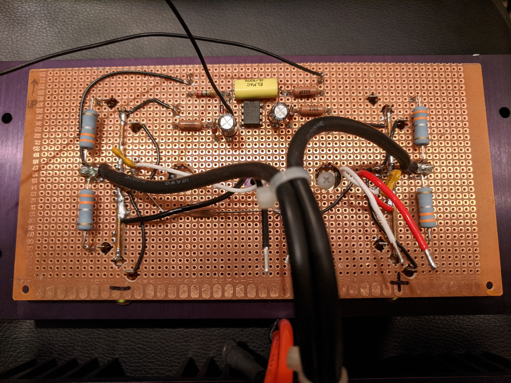
BJT output stage board with DC servo.
Links to Japanese SA-12 repair pics:
www.amp8.com/tr-amp/foreign/counterp/cosa12-2.htm
www.amp8.com/tr-amp/foreign/counterp/coposa12.htm